


In our last article, we looked at how a pipe stress analysis is carried out. One of the outputs of such an analysis is the loads on the restraints. It is these loads that serve as the inputs to the pipe support design. The next step in the piping design process is to convert the analysis results into a properly functioning support system.
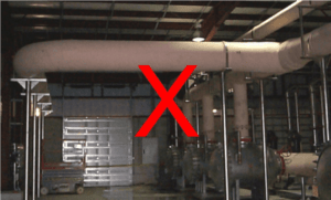
In any piping system, it is necessary that the support and support system be configured to behave as intended in the piping design. The support must be physically configured to provide the type of restraint that was assumed in the design. For example, if the particular support was intended to act as a guide, i.e. to provide lateral restraint for loads such as wind or seismic, then it must be strong enough and stiff enough in the lateral direction to provide the required restraint. The photo below indicates a situation where the guides were not properly configured. Being on tall posts like this results in the supports having very little lateral stiffness. The piping will therefore be allowed to deflect laterally to a much greater extent than would likely have been assumed in the design.
With an FRP piping system, there are additional support considerations that must be borne in mind. These include the following:
- FRP piping should never be supported directly on steel structure.
- Supports should be configured to avoid point loads on the FRP pipe.
- Supports must be stiff enough to keep the pipe round.
- Supports must be sized to properly fit the pipe.
- In-line equipment should be independently supported.
- Supports should be located to avoid interference with pipe joints.
Let’s look at these points in a little more detail.
FRP is a non-ductile material. That means it won’t yield and redistribute local high stresses in the same way as a ductile material would. It is therefore necessary to ensure that the pipe is not exposed to point loads, or even to line loads.
Supports should include elastomeric liners to act as cushioning to soften any point loads. FRP pipe typically has an irregular outside surface, so resting the pipe directly on steel, or even using steel saddles without the elastomeric linings can result in point loads on the pipe.
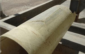
Apart from the need to avoid point loading, FRP pipe should never be supported directly on steel simply because any relative movement can lead to chafing damage of the FRP pipe. The photo below illustrates what can happen when FRP pipe is supported directly on a steel beam. The pipe experienced a very high stress along the line of contact between the pipe and steel, and it actually failed along this line.
Supports should also provide sufficient bearing area to distribute the load over a reasonable area of the pipe. It is common to specify a minimum length of a support to be ¼ – ⅓ of the diameter of the pipe. A good rule of thumb is to ensure the bearing stress is limited to not more than 50 psi.
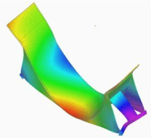
A commonly over-looked requirement for FRP pipe supports is the need for adequate support stiffness. When the pipe is under loads, the job of the support is to transfer the loads to the support structures, but in doing so it must also hold the pipe round. FRP pipe is much less stiff than steel pipe, so it could ovalize if the support were not sufficiently stiff. This would lead to high local stresses in the pipe, and a reduction in the ability of the pipe to act as a beam, i.e. to span between supports. Small diameter pipe is proportionately stiffer than large diameter pipe, so a minimum saddle angle of 120 deg is usually adequate. For larger diameter pipes, a minimum saddle angle of 150 deg is recommended, and supports should be properly stiffened to hold their shape. If supports are not designed to provide adequate stiffness, the support can deform significantly under load as illustrated in this computer graphic.
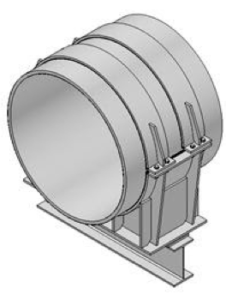
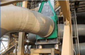
The image below illustrates the configuration of a properly designed weight support. Note the webbing and gusseting that ensures the support will retain its round shape.
FRP pipe typically does not have the same outside diameter as steel pipe, so it shouldn’t be assumed that a support intended for steel pipe will properly fit FRP pipe. This is particularly true in larger diameters where the outside diameter of the FRP pipe does not match the nominal size of the pipe (as it does for steel pipe). In FRP pipe, the nominal size of the pipe typically matches the inside diameter of the pipe, so the mismatch between the outside diameter of the pipe and the inside diameter of a steel pipe support can be significant. The supports should be designed to match the outside diameter of the FRP pipe. RPS provides a complete line of pipe supports designed specifically with this in mind, thereby eliminating any concern about proper fit of the supports.
FRP pipe has a relatively low allowable axial stress, so it is important that supports be included at or near heavy in-line equipment. It is good practice to include supports at all valves as illustrated in this photo.
It is important to locate supports to avoid pipe joints. The overall width of an FRP pipe joint is typically in the range of about one pipe diameter. Piping layout and support locations should be chosen with this in mind. If there is no other choice, the piping can be configured to accommodate a support on or at least near a joint, but this usually increases the cost significantly.
Adhering to these basic principles when designing and fabricating the supports for an FRP piping system will go a long way to ensuring trouble-free performance of the piping system, and purchasing the supports from RPS will provide peace of mind that these principles have been properly addressed.
Next article in the series: How Pipe Stress Analysis is Carried Out
Next in the series: FRP Pipe Installation