


In our last several articles, we have looked at the piping information required to properly analyze an FRP piping system. This information included the elastic properties (modulus values and Poisson ratios), the strength properties (allowable stress envelopes), and the Stress Intensification Factors and Flexibility Factors. We’re now at a point where we can discuss how a pipe stress analysis is actually carried out.
As previously mentioned, there are inputs to the pipe stress analysis that would be the same regardless of the choice of piping material. These include pressure, temperature, and density of the fluid, which are dictated by the process conditions. They also include the occasional loadings such as wind and seismic. The Owner (or Owner’s agent) will typically define the basic occasional load parameters such as wind speed and seismic accelerations, as well as the building code to which all plant equipment and systems must be designed. The Designer will then utilize the provisions of a building code standard such as ASCE 71 to determine the actual loads that should be included in the pipe stress analysis.
The Designer creates a computerized model of the piping system with a pipe stress analysis program such as CAESAR II or AutoPIPE. This task involves a number of steps including:
- Breaking the piping system into discrete elements, each of which represents a small portion of the piping system. The elements are defined by the “nodes” at each end of the elements. The choice of node locations is up to the Designer, but for accurate representation of the piping system, nodes are required at each change of direction or material, at all in-line equipment, and at all restraints (supports and terminal points). Additional nodes would be included at any location where the Designer requires output information. An example of this would be at the midpoint between supports so that the deflection between supports can be determined.
- Defining the appropriate geometric properties of each element, i.e. diameter and thickness of the pipe, and length and orientation of the element.
- Defining the design conditions/loadings including pressure, temperature, weight of the pipe and contents, and seismic and wind loadings.
- Assigning the appropriate material properties to each element including modulus values and allowable stresses.
- Applying the appropriate Stress Intensification Factors and Flexibility Factors to the fittings.
- Defining the support types and locations.
- Defining any imposed displacements on the piping system, e.g. thermal growth of a vessel to which the piping is attached.
- Creating the appropriate load cases to ensure all load combinations of interest are analyzed.
An example of the input screen (CAESAR II) defining the properties of a particular element is shown below:
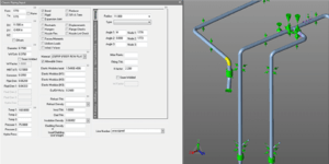
When all the inputs have been entered into the model, the analyses are run. The Designer reviews the results including the piping stresses, piping deflections, and loads on restraints to determine if the design is acceptable.
If the stresses due to pressure plus weight or occasional loads (seismic and wind) exceed the allowable stresses, or if the deflections between supports exceed the allowable deflections, the Designer will typically add restraints to the system. The additional restraints will often be sufficient to solve the stress/deflection problems due to these primary loads, but there may still be stress problems due to constraint of thermal expansion. The piping will try to expand when exposed to an increase in temperature, and some means must be provided to accommodate that expansion. The methods that are typically used include:
- Utilizing the flexibility inherent in the piping layout due to changes in direction
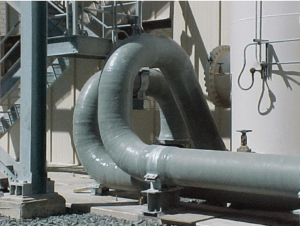
- Introducing expansion loops
- Introducing expansion joints
Another method that is commonly used to control thermal expansion in FRP piping systems is to rigidly restrain straight runs of pipe. Due to the relatively low axial modulus of FRP pipe, the thermal compressive stresses in the pipe and the loads at the anchors are often quite manageable, but this method of support is typically limited to smaller sizes of pipe or to systems where the change in temperature is modest.
While it is necessary to include sufficient restraints to limit the stresses or deflections due to weight and occasional loads, too many restraints can result in flexibility problems with the piping. In fact, the process of arriving at a suitable piping system design often comes down to finding an acceptable balance between providing enough supports to handle the primary loads (weight, seismic, and wind), and providing sufficient flexibility to accommodate the thermal expansion. This process typically requires several attempts at defining an acceptable configuration for the number, types, and locations of the supports.
Apart from the stresses and deflections, the pipe stress analysis also provides the loads on the restraints. It is these loads that are used to design the pipe supports. This task is a necessary part of any pipe system design, but there are particular aspects of the support design for FRP piping that require special attention. Support design for FRP piping will be the subject of our next article.
1 ASCE 7 Minimum Design Loads for Building and Other Structures
Previous article in the series: Stress Intensification and Flexibility Factor
Next in the series: Properly Functioning Support System