HOME > Resources > Technical Center > Elastic Properties
Elastic Properties
In our last article, we began our look at the issues associated with FRP piping system design and analysis. We discussed several levels of analysis, from rules of thumb to comprehensive computer analysis. We also discussed the goals of a pipe stress analysis as well as the primary difference between analysis of FRP piping systems and that of metallic piping systems. In this article we are going to begin our look at what information is needed to carry out a stress analysis of an FRP piping system and where that information can be obtained.
To carry out any pipe stress analysis, there are a number of piping system properties that must be known in advance. Some of these properties, such as fluid pressure, temperature, and density, are dictated by the process and would be the same regardless of what piping material was used. Other properties are dependent on the piping material and include physical properties (e.g. density), thermal properties (e.g. coefficient of thermal expansion), and mechanical properties (e.g. modulus of elasticity and strength). Of these properties, we’re going to focus on the mechanical properties, which are typically divided into the elastic properties and the strength properties (from which we can determine the allowable stresses).
The elastic properties include the modulus of elasticity values and the Poisson ratios. The modulus of elasticity is a measure of the material’s resistance to deformation when a force is applied to it. The higher the modulus, the less the material will deform, i.e. the “stiffer” the material is. The Poisson ratio is a measure of how much a material will deform in one direction when a load is applied in another direction. For example, if an axial load was applied to a pipe, the tensile modulus of elasticity will tell us how much the pipe elongates in the axial direction, and the Poisson ratio will tell us how much the pipe will shrink in the hoop direction.
For isotropic materials such as steel, there are 3 elastic properties that must be known:
- Young’s modulus of elasticity (or tensile modulus of elasticity, usually given the symbol E)
- Shear modulus of elasticity (usually given the symbol G)
- Poisson ratio (typically given the symbol ν, i.e. Greek letter “Nu”)
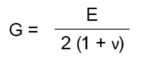
For isotropic materials, these three properties are related to each other by the following equation:

So it is only necessary to know two of the values, as the other property can be determined by this relationship. Appropriate values for these properties are listed in the ASME Piping Codes such as B31.1 “Power Piping” and B31.3 “Process Piping”.
For steel, typical values of these properties are:
E = 29 x 106 psi (200,000 MPa)
G = 11 x 106 psi (77,000 MPa)
ν = 0.3
For orthotropic materials like FRP, there are 5 elastic properties that must be determined:
- Axial modulus of elasticity (usually given the symbol Eaxial or Ea)
- Hoop modulus of elasticity (usually given the symbol Ehoop or Eh)
- Shear modulus of elasticity (usually given the symbol G)
- Major Poisson ratio (usually given the symbol ν1 or νx)
- Minor Poisson ratio (usually given the symbol ν2 or νy)
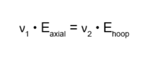
The axial and hoop modulus values and the Poisson ratios are related by:

So only 4 of the 5 properties must be known, as the fifth can be determined by this relationship.
For 55 deg. filament wound pipe, typical values of these properties would be:
Eaxial = 1.4 x 10⁶ psi (8,965 MPa)
Ehoop = 2.3 x 10⁶ psi (15,860 MPa)
G = 1.5 x 10⁶ psi (10,345 MPa)
ν1 = 0.72
ν2 = 0.44
As you can see, the modulus values are significantly less than those for steel. In particular, the axial modulus of elasticity is less than 1/20th that of steel, which means FRP pipe is significantly more flexible than steel pipe. That fact can be quite helpful in that it makes offset legs in piping systems very effective at absorbing thermal expansion of the piping. But we also have to be careful to limit support spans to more modest values than for steel pipe to ensure the deflection between supports is not excessive.
The elastic properties can vary widely depending on the construction of the FRP laminate. The format of the reinforcement and the orientation of the fibers in particular can have a huge effect on these properties. The properties can be determined by testing samples of the material, and this is often done for “standard” laminates. That is, for pipe products that are manufactured using a specific and fixed construction (resin system, glass type, fiber format, fiber orientation, and laminate sequence), determination of these properties by testing is a practical approach.

However, one of the distinct advantages of using a composite material like FRP, is the ability to custom-design a laminate to suit the specific application. This could mean anything from selecting a different resin, to changing the corrosion barrier construction, to adding directional reinforcements, to changing the entire laminate sequence. It would be impractical and cost-prohibitive to conduct testing on all such potential solutions to a given problem. Fortunately, there are mathematical procedures available that allow us to calculate the elastic properties of these various constructions. These procedures are addressed by the field of Mechanics of Composites.
The mathematics associated with Mechanics of Composites can appear a bit daunting to those not familiar with it, e.g.


But many manufacturers and designers of FRP equipment use these principles on a daily basis and are well qualified to take full advantage of them.
Mechanics of Composites includes two subjects of direct relevance to our current discussion, i.e. Micromechanics and Lamination Theory. Micromechanics provides a method of determining the properties of individual layers (or “lamina”) from the properties of the constituent materials (resin and glass) and from the configuration of the layer, i.e. thickness, glass content, fiber format, and fiber orientation. The field of micromechanics is largely empirical, and there have been several micromechanics theories developed over the years to attempt to accurately predict lamina elastic properties. One of the most widely accepted theories is that presented in Military Handbook 17, and it is this theory that has been adopted in ASME NM.21, ASME RTP-12, and ASME Section X3.
Once the elastic properties of each layer are known, we can combine the properties of all the layers using Lamination Theory to determine the overall elastic properties of the laminate. Lamination Theory is well developed and will yield very good predictions of elastic properties of laminates. We can then use those elastic properties as inputs to a pipe stress analysis.
In our next article, we will continue our discussion on mechanical properties required for a pipe stress analysis by looking at the allowable stresses.
1 ASME NM.2 “Glass Fiber-Reinforced Thermosetting Resin Piping”
2 ASME RTP-1 “Reinforced Thermoset Plastic Corrosion-Resistant Equipment”
3 ASME BPV Code Section X “Fiber-Reinforced Plastic Pressure Vessels”
Previous article in the series: FRP Piping System Design
Next article in the series: Strength Properties


